
 沖擊電壓發生器/沖擊電流發生器
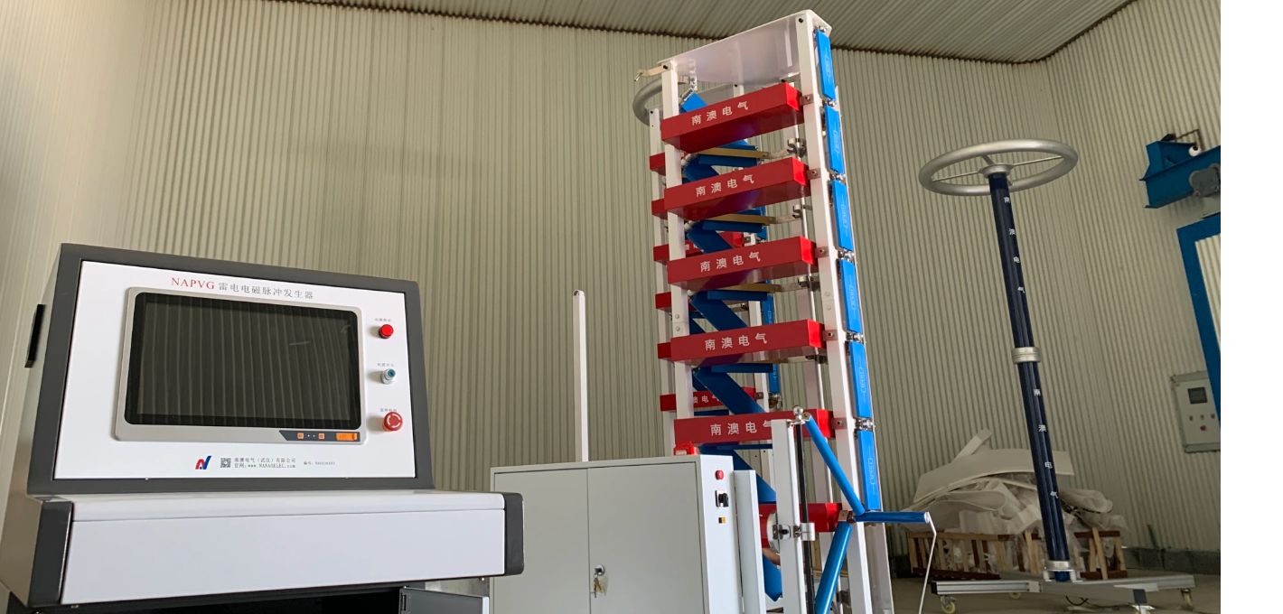
NAICH多分量波形全自動雷電沖擊電流發生器試驗裝置
NAICH multi-component waveform automatic lightning impulse current generator test device
產品別名
多分量波形沖擊電流試驗裝置,四分量波形沖擊電流裝置,4分量波形沖擊電流試驗,D分量波形沖擊電流裝置,多分量沖擊電流試驗,四分量雷電沖擊電流,分量波形沖擊電流試驗,分量波形沖擊電流發生器裝置,多分量雷電沖擊電流,多分量波形雷電沖擊,四分量沖擊電流發生器,分量雷電沖擊電流,分量波雷電沖擊,多分量沖擊電流試驗裝置,分量波形雷電沖擊,D分量波沖擊發生器
設備概述
本套多分量波形全自動雷電沖擊電流發生器試驗裝置,可用于飛機整機、飛機局部艙段或發動機組件的雷電防護測試,確定飛機電氣系統線纜上的實際感應電平及瞬態波形,確定或驗證雷電防護相關的瞬態控制電平和設備瞬態設計電平。發生器也可用于燃油系統的非電氣系統導體(如控制線纜、燃油、液壓、氣壓管路以及結構件)或系統效應的測試。
本系統輸出D分量峰值100kA,T1≤30μS,T2≦500μS(指數波形或震蕩波形)。
依據標準
GB 18802.1-2011 低壓配電系統的電涌保護器(SPD):性能要求和試驗方法
GB/T 18802.12-2011 低壓配電系統的電涌保護器(SPD):選擇和使用導則
IEC 61643-1-2011 Low-voltage surge protective devices –Part 1:Surge protective devices connected to low-voltage power distribution systems –Requirements and tests
IEC61643-12-2011低壓浪涌保護裝置:連接到低壓配電系統的電涌保護裝置.選擇和應用原理
UL1449-2015 Surge protective devices
f) YD/T 1235.1-2002通訊局(站)低壓配電系統用電涌保護器技術要求
g) YD/T 1235.2-2002 通訊局(站)低壓配電系統用電涌保護器測試方法
h) GB/T 16927.1-1997高電壓試驗技術 一般試驗要求
i) GB/T 16927.2-1997高電壓試驗技術 測量系統
j) YD/T 5098-2001通信局(站)雷電過電壓保護工程設計規范
k) GB3567-99 飛機雷電防護鑒定試驗方法
l) GB/T 17626.5-2018 電磁兼容 試驗和測量技術 浪涌(沖擊)抗擾度試驗
主要參數
輸入電源:交流,50Hz/60Hz
變壓器:油浸式單相,380V/70kV/10kVA,
充電電壓:DC80kV,充電電流0.1A
充電極性:正負極性可自動變化
充電時間:輸出100kA電流每60s充放電一次,
結構型式:多臺扇形布置,可單獨放電,也可聯合放電。
沖擊電容器: 10臺沖擊電容器
高壓油浸電容器參數:80kV/2μF
單臺沖擊總能量:6.4kJ
單臺沖擊總能量:64kJ
電容器壽命:正常工況下,設備額定充放電次數超過20萬次,80%額定電壓下,可長期使用。額定輸出運行時,預留余量大于10%。
主要組成部件
本體扇形結構
本體電容器采用扇形結構,電容器垂直放置, 底部連接固定;
本體電容器采用扇形向心對稱結構,從結構上確保每組電容器距離放電間隙距離相同,很好地保證放電電流的均勻性。在長期使用中這樣的結構設計可以保證電容器使用壽命均勻,從而延長了設備壽命。
電容器可以單組運行,也可以并聯運行,手動換接電路比較方便。每組電容器放電過程中均串聯電阻,能夠保證電容器安全運行。
NAICH Multi-component Waveform Automatic Lightning Impulse Current Generator Test Device
Also Called Name
Multi-component waveform impulse current test device, four-component waveform impulse current device, 4-component waveform impulse current test, D-component waveform impulse current device, multi-component impulse current test, four-component lightning impulse current, component waveform impulse current test, component waveform impulse Current generator device, multi-component lightning impulse current, four-component impulse current generator, component lightning impulse current, component wave lightning impulse, multi-component impulse current test device, component waveform lightning impulse, D-component wave impulse generator
Equipment Overview
This set of multi-component waveform automatic lightning impulse current generator test device can be used for the lightning protection test of the aircraft, the aircraft's partial cabins or the engine components, and determine the actual induction level and transient waveforms on the aircraft electrical system cables. Determine or verify the transient control level and equipment transient design level related to lightning protection. The generator can also be used to test the non-electrical system conductors of the fuel system (such as control cables, fuel, hydraulic, pneumatic lines and structural parts) or system effects.
The system output D component peak value 100kA, T1≤30μS, T2≤500μS (exponential waveform or oscillating waveform).
According Standards
a) GB 18802.1-2011
b) GB/T 18802.12-2011
c) IEC 61643-1-2011 Low-voltage surge protective devices –Part 1:Surge protective devices connected to low-voltage power distribution systems –Requirements and tests
d) IEC61643-12-2011
e) UL1449-2015 Surge protective devices
f) YD/T 1235.1-2002
g) YD/T 1235.2-2002
h) GB/T 16927.1-1997
i) GB/T 16927.2-1997
j) YD/T 5098-2001
k) GB3567-99
l) GB/T 17626.5-2018
Main Data
Input power: AC, 50Hz/60Hz
Transformer: oil-immersed single-phase, 380V/70kV/10kVA,
Charging voltage: DC80kV, maximum charging current 0.1A
Charging polarity: positive and negative polarity can be changed automatically
Charging time: output 100kA current to charge and discharge once every 60s,
Structure type: Multiple units are arranged in a sector, which can be discharged individually or in combination.
Impact capacitor: 10 impact capacitors
Parameters of high-voltage oil-immersed capacitors: 80kV/2μF
Total impact energy of a single unit: 6.4kJ
Total impact energy of a single unit: 64kJ
Capacitor life: Under normal operating conditions, the rated charge and discharge times of the equipment exceed 200,000 times, and it can be used for a long time under 80% of the rated voltage. When the rated output is running, the reserve margin is greater than 10%.
Main Components
Body Sector Structure
The body capacitor adopts a sector structure, capacitor is placed vertically, and bottom is connected and fixed;
The body capacitor adopts a fan-shaped centripetal symmetrical structure to ensure that each group of capacitors is at the same distance from the discharge gap to ensure the uniformity of the discharge current to the greatest extent. In long-term use, such a structural design can ensure the uniform life of the capacitor, thereby prolonging the life of the device.
Capacitors can be operated in a single group or in parallel, and it is more convenient to switch the circuit manually. Each group of capacitors are connected in series with resistors during the discharge process, which can ensure the safe operation of the capacitors.
南澳電氣武漢公司 版權所有 NANAO ELECTRIC. Copyright ? 2004-2018, www.tisnys.cn All Right Reserved. 備案號:鄂ICP備16008747號-2
服務熱線
